Overview:
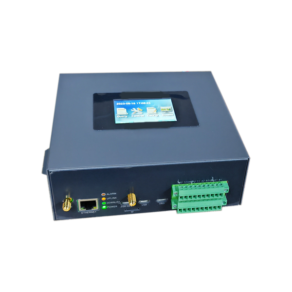
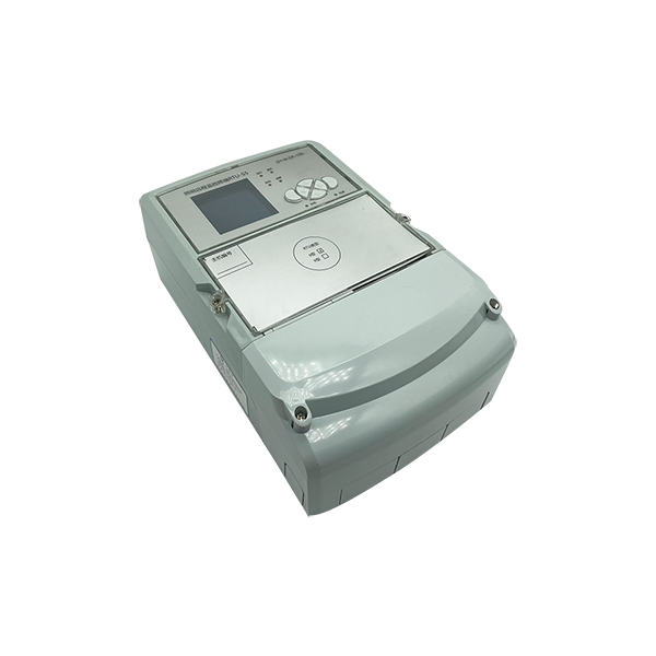
Lighting Power Cabinet (LPC)controller is a multi-functional, high-performance, and
modularized design RTU (Remote Terminal Unit) for feeder pillars or power cabinets. Installed inside the cabinet, the LPC controller can not only enable monitoring and control of lighting power, but also carry out the measurements and diagnoses of electrical parameters in the lighting grid. It can be applied to these scenarios: road lighting, landscape lighting, tunnel lighting, building lighting, etc.
Product Features:
- Meter-type design installed inside the feeder pillar or power cabinet;
- Uplink communication supports 4G/GPRS/Ethernet.
- Downlink communication supports Zigbee 2.4GHz or PLC, working with a counterpart Zigbee 2.4GHz or PLC streetlight controller to effortlessly achieve individual lamp control.
- Integrated LCD screen to display important info and data.
- Remote management of street light – group switch on / off.
- Built-in meter-level chip to accurately measure electrical data such as 3-phase voltage and current, power, KWh, and so on.
- Built-in battery supports the equipment to continue working even if the power is outage.
- Accurate RTC unit embedded, supports automatic operation of switching on / off based on predefined schedules.
- Connecting interface: RS485 / RS232;
- Holds DO (Digital output) * 8, DI (Digital input) * 16;
- Supports 6 channels of voltage measurement and 21 channels of current measurement;
- Peripheral sensor functions are available: water immersion sensor / light sensor / door sensor / electricity leakage detection / temperature measurement.
- With a wealth of expandable features, it can realize a variety of flexible switching tasks.
- Malfunction detection and alarm are actively by means of noise or notification;
- Secure communication by encryption AES 128b;
- IP54;
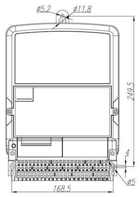
Mechanical layout design drawing
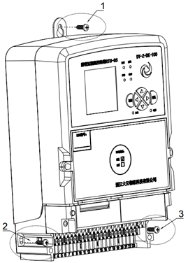
Wiring diagram
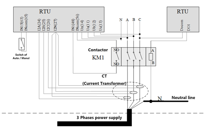
Notice:
1. A 3P 5A circuit breaker must be added for input line voltage detection;
2. The current collecting transformer must ensure that the secondary side does not open circuit;
3. All current transformers should be installed in the same direction, for example: cables enter from P1 and exit from P2, and transformer S2 is connected to IxN (common terminal).