
Browse products and models

Street Light Controller
CX-Box Streetlight Controller
- Communication
- PLC (10-500 kHz)
- Connection
- Wired box installation
- Ingress protection
- IP68
Product features
Connected Control for Individual Street Lights
- Compact box design for installation inside an LED fixture or a lamp-post manhole.
- PLC communication over the existing lighting power circuit.
- Remote ON/OFF control and compatible 0-10V dimming.
- Real-time luminaire status, electrical data and fault monitoring.
- Automatic operation using predefined schedules and adaptive lighting strategies.
- Power-loss detection and active fault reporting by the management platform.
- AES 128-bit communication encryption.
- IP68 enclosure for demanding outdoor installation environments.
Technical data
Product Parameters
| Parameter | Specification |
|---|---|
| Model | DYSLC10 |
| Dimming interface | 0-10V |
| Power outage detection and reporting | Supported |
| Remote control | ON / OFF / Dimming |
| Power supply | 85-265 V AC / 50-60 Hz |
| Maximum power consumption | < 3 W |
| Load rating | 5 A / 250 V AC |
| Measurement accuracy | +/- 2% |
| Communication network | PLC |
| Communication frequency | 10-500 kHz |
| Communication security | AES 128-bit |
| Operating temperature | -40 C to 85 C |
| Operating humidity | <= 95% RH at 25 C |
| Ingress protection | IP68 |
| Dimensions | 150 x 60 x 37 mm |
| Weight | 600 g |
Installation instructions
Installation and Wiring
- Disconnect and verify the absence of electrical power before installation.
- Install the controller inside the LED fixture or inside the lamp-post manhole, with sufficient space and cable protection.
- When the controller is installed inside the fixture, route the antenna outside or to a nearby suitable position.
- Mount the antenna above 2.5 m on the pole; seal the 10 mm mounting hole to maintain waterproof protection.
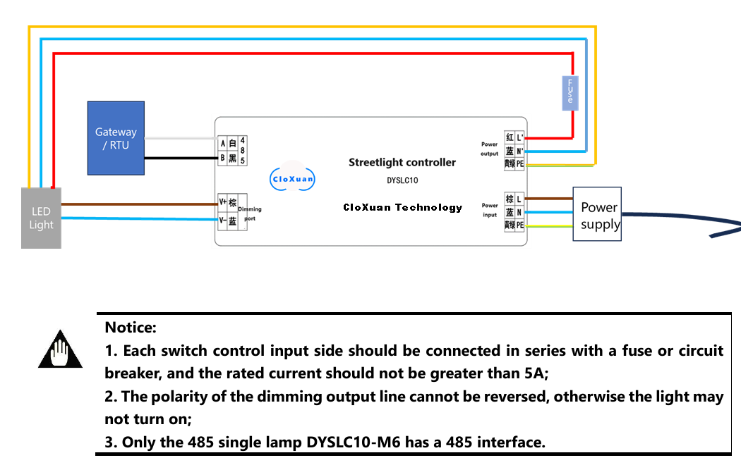
- Do not reverse the power input and output wires, and connect the PE conductor reliably to earth.
- Protect the switch-control input with a fuse or circuit breaker rated no higher than 5 A.
- Observe the polarity of the 0-10V dimming output before restoring power.
- Commission the controller and verify switching, dimming, data and alarm reporting.
| Connection | Function | Definition | Cable / Remark |
|---|---|---|---|
| Brown (L) | Power input | Input live wire | 3-core sheathed cable |
| Blue (N) | Power input | Input neutral wire | 3-core sheathed cable |
| Yellow-green (PE) | Protective earth | Connect to earth | 3-core sheathed cable |
| Red (L') | Power output | Output live wire to load | 2-core sheathed cable |
| Blue (N') | Power output | Output neutral wire to load | 2-core sheathed cable |
| Brown (V+) | Dimming output | DC 0-10V positive | 2-core sheathed cable |
| Blue (V-) | Dimming output | DC 0-10V negative | 2-core sheathed cable |
| White (A) | RS485 | Signal line A | DYSLC10-M6 only |
| Black (B) | RS485 | Signal line B | DYSLC10-M6 only |

Safety: Installation and maintenance must be completed by qualified personnel with electrical power isolated. Follow the approved model-specific manual and applicable local electrical regulations.