Overview
DY-RTU10-ZIGBEE can realize functions such as timing switch control, power consumption measurement, running status of cabinet monitoring, and remote management. Via the interface of RS485 and DI/DO, it enables expansion of numerous features like door open detection, temperature monitoring for the cabinet, rainfall detection, etc. Built-in meter-level measurement chip, it can provide accurate data of energy data consumed by lights. The embedded touch-color-screen can display rich and important data, which is helpful for the maintenance crew at the site. Since it has integrated with a Lithium battery, the concentrator can continue to work in case of an outage. With a wealth of features, it can be used in numerous scenarios like road lighting, public lighting, tunnel lighting, façade lighting, and other fields.
Product Features:
- Compact design for conveniently installing inside a feeder pillar or other waterproof cabinet.
- Uplink communication supports 4G/GPRS/Ethernet.
- Downlink communication supports Zigbee 2.4GHz, working with the counterpart Zigbee 2.4GHz streetlight controller to effortlessly achieve individual lamp control.
- Max point-to-point comm distance is 200 M, after meshing, it can transmit up to 1500 M in visible distance, communication speed is 250kps.
- Integrated touch-color LCD screen to display important info and data;
- Remote management of street light – group switch on / off;
- Built-in meter-level chip to accurately measure electrical data such as 3-phase voltage and current, power, kWh, and so on.
- Built-in battery supports the equipment to continue working even if the power is outage.
- Accurate RTC unit embedded, supports automatic operation of switching on / off based on predefined schedules.
- Connecting interface: RS-485.
- Holds DO (Digital output) * 8, DI (Digital input) * 4;
- Peripheral sensor functions are available: light sensor / rainfall sensor / vehicle flowing.
- With a wealth of expandable features, it can realize a variety of flexible switching tasks.
- Malfunction detection and alarm are activated by means of noise or notification.
- Secure communication by encryption AES 128b.
- Support OTA upgrade.
- IP54.
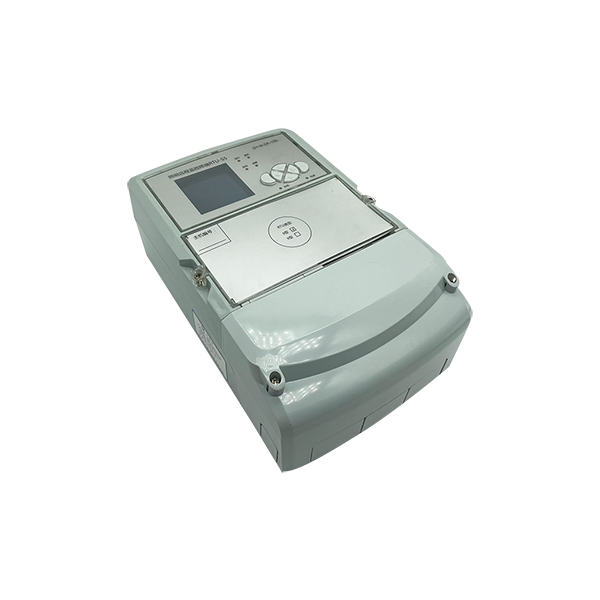
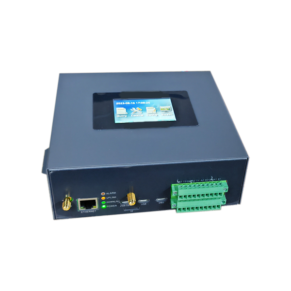
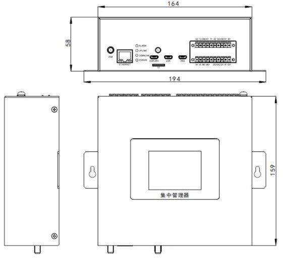
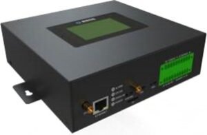
Size and picture

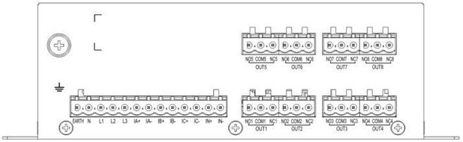
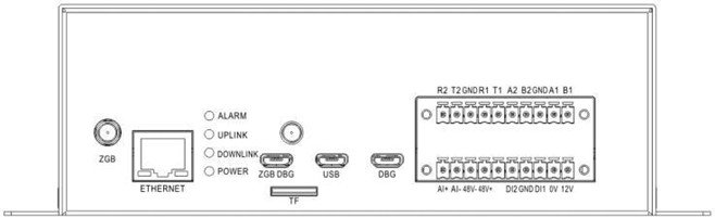
Connection ports